The Capstone Microturbine Generator
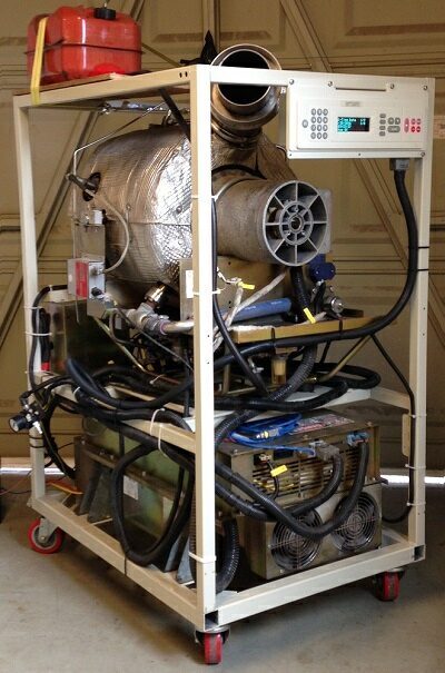
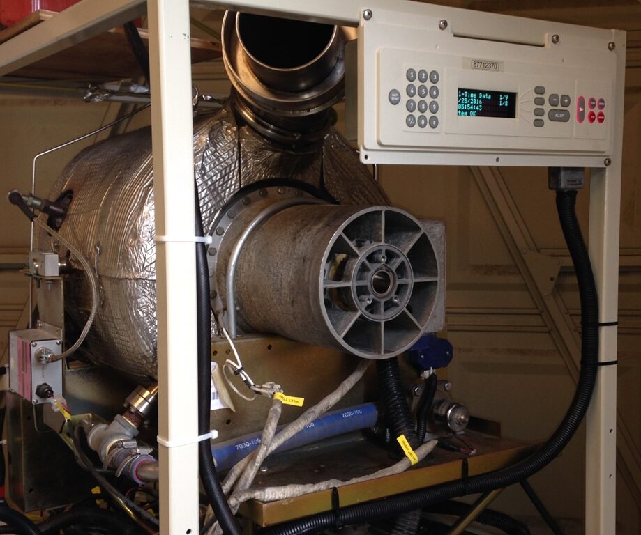
A truly remarkable piece of turbo-machinery the Capstone microturbine generator is a mile stone in world gas turbine and microturbine development. Built by Capstone Green Energy no other engine have every been built like it, the C30 belongs to a three model range that all adopt the same innovative construction and layout. An economic and long life microturbine is a significant technical challenge and the C30 comes closest to for-filling this goal but remains an expensive machine double the costs of a reciprocating equivalent.
See Also-
Microturbines Guide, History and Blog
Capstone Microturbine Specification C30 HEV
Compressor…………........………………………………………..single stage centrifugal impeller
Combustor………….......………………………………….annular with three atomising burners
Recuperator………........……………………………………………….. static radial heat exchanger
Turbine………………......…………………………………………………………………………..radial inflow
Layout……………….......……………………single shaft with high speed alternator (PMG)
Lubrication………….......……………………………………………….…..none, air bearing system
Fuel system……….........………electric motor metering pump, air assisted atomisers
Starting………………………………………………………………synchronous motoring by PMG
Ignition…………………………………………......…………high energy surface discharge plug
Control system…………………………………………...….…………embedded micro processor
Maximum Power Output……………………….....………………………29Kw at 96,000 rpm
Minimum Power Output …………………..…………………………………1Kw at 45,000 rpm
Fuel……………....………………………………………………..……………..kerosene, diesel Bio fuel
Fuel Consumption at full load (Source MME)…………………………………….11L/hour
Accessories…....Digital Power Controller(DPC), Battery Pack, operator control panel, GUI software.
Approximate size…………....…………….……..…….1m x 1m x 2m not inc battery pack
Weight…………………………..…………………….…………..80kg not including battery pack
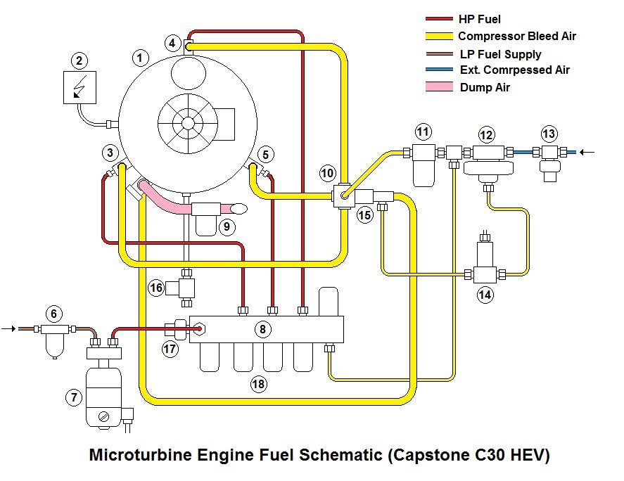
1. Microturbine engine
2. Igniter
3. Injector #1
4. Injector #2
5. Injector #3
6. LP fuel filter
7. HP fuel pump
8. Fuel distribution manifold
9. Compressor dump valve
10. Air distribution manifold
11. Air assist solenoid valve
12. Differential pressure regulator
13. Pressure switch
14. 3-way solenoid valve
15. Check valve
16. Drain valve
17. Fuel pressure switch
18. Injector solenoids
The small gas turbine is a remarkable piece of machinery but also a comparatively rare one. As prime movers go the ratio of gas turbines to piston engines around the World must be less than one in a million! Small GTs are generally confined to aviation and may be found in applications such as auxiliary power units (APU) in aeroplanes and helicopters, turbo-propeller propulsion engines in medium weight aeroplanes and as the power plant in light to medium size helicopters. It is a device that finds applications in aerospace, military and the oil, gas and power industries, but outside of these, this highly developed, expensive and precision device is rarely found. The gas turbine is not a domestic” animal! In the last 20 years and particularly during the age of the Internet so far, they now exist in a number of forms that the “civilian” consumer world has access to but very much still confined to niche areas.
Small gas turbines may be divided in to four distinct categories with little overlap, they are; aerospace developed and manufactured units, radio control model power plants, turbocharger derived units and microturbines. They may be described as follows-
Aerospace; A small gas turbine engine of power output up to 500 hp (350 Kw) providing shaft, pneumatic, electrical or hydraulic power for use in aircraft and helicopters. Also as ground support and starting equipment.
Microturbine; The microturbine may be considered a unique breed of small gas turbine engine power plant in its own right. In power generation very large gas turbines are normally operated producing megawatts of power, a small gas turbine producing only a few tens of kilowatts in comparison is of “Micro” size and hence the designation microturbine. Commercial microturbine models having been built in volume production, range in power output from just 2.6KW (probably the World’s lowest rated production gas turbine) to around 250Kw. Until now microturbine applications have consisted of installations providing combined heat and power (CHP) or where a supply of waste product fuel gas is available of sufficient quality to support combustion in a gas turbine. CHP is usually where the waste heat from the gas turbine after having produced electricity is used to heat a building as part of a heating ventilation and air conditioning (HVAC) installation. There may be occasions where the abundance of quality heat output may be used as part of an industrial process and where the electricity generated is used also. Now there is the prospect of these devices becoming used for power generation on board a vehicle in the form of a “range extender”. A range extender is basically a device to aid the recharging of an electric vehicle battery whilst on the move.
There are areas where these categories of power plant cross over for instance RC turbines may be used in professional applications as propulsion for military of civilian drones and un-manned aircraft. Turbocharger type units may be used as smoke generators. All categories may find themselves applied to education and research, any type of gas turbine might be found in a University or Technical college laboratory. It is the microturbine category that this document seeks to focus on.
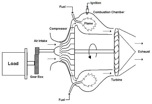
The microturbine engine working cycle is the same as all conventional gas turbines small and large. The component parts are similar with the addition of an extra device known as a recuperator.
The microturbine consists of a centrifugal compressor wheel and a turbine wheel mounted on a common shaft. This assembly rotates at high speed and is supported by special bearings. In the case of many microturbine designs (but not all) the shaft is also coupled directly to an electrical generator that also acts as the starter.
The working cycle is initiated by the starter often formed by the generator being operated in reverse as a motor. As the shaft rotates the compressor wheel draws in air that is compressed by the action of the wheel itself and a surrounding stationary component known as the diffuser. In a basic engine design the air from the compressor is passed to a combustion system. The combustion system is formed by a chamber that mixes the air from the compressor with fuel that is burned. The fuel air mixture is initially ignited during starting by an electrical spark igniter, once lit it burns continuously until the engine is shut down. The resulting combustion introduces heat in to the working cycle creating gases that expand as they get hot and exit the combustion chamber with added energy. The hot gases are directed through another stationary component a nozzle that directs streams of hot gases that impinge on the turbine spinning it around. As the compressor and turbine rotate, they accelerate under the combined action of the starter and the hot gas stream, as speed increases the compressor discharge pressure also increases overcoming thermodynamic and mechanical losses and a point is reached where the cycle is self-sustaining. Once self–sustaining, the process no longer requires the assistance of the starter and it is turned off. The process continues and the rotor eventually reaches a governed speed controlled by heat input and hence the fuel flow. A load may then be applied to the engine and useful power extracted.
The gas turbine in its simplest concept may be likened to a windmill or turbine connected to a fan or propeller. If this arrangement is rotated, wind from the fan would impinge on the turbine and drive the whole thing around. This would be perpetual motion and of course does not work! If heat is added (a source of external energy) between the fan and the windmill then the air expands and hits the windmill with increased ferocity creating a force that could assist in driving it around. In practice this still does not work as the losses (air escapes and leaks around components) are very high and the net forces at atmospheric pressure are very low and are not able to overcome mechanical losses and friction. The individual component efficiencies could be improved by enclosing them in a housing, making the fan in to an impeller shaped wheel, sculpturing the turbine and tailoring the gas flow in and out of it. If this arrangement is spun around by an external driving force (starter), and if it is spun fast enough with sufficient heat added (but not too much as to melt the hot components), then the process will become self supporting and the device runs on its own. This is the gas turbine principal, a device has been created that drives itself and expels hot gases in its exhaust. If a restricting nozzle is place in the exhaust, the gas velocity may be increased, a combination of the pressure drop across the nozzle exit diameter and the accelerated mass flow of gas though it creates a reaction on the whole engine assembly that is known as thrust. The gas turbine has become a simple jet engine!
The gas turbine working cycle is driven by the heat input to it between the compressor outlet and the turbine inlet. This heat normally comes from the combustion of fuel with a flame, it can come from other sources such as an external heat source via a heat exchanger or even an electrical heater. An electrically fired gas turbine could be produced but the heating intensity would have to be quite large (to mimic that that is normally produced by a steady flame) and or the combustor assembly made quite large also to fully heat all the air to the required turbine inlet temperature.
In an operating gas turbine considerable power is absorbed by the compressor and once started it is all provided by the turbine. When these components are optimized within the operating temperature range of the turbine material, additional power is available from the connecting shaft to drive an external load e.g. the generator. In a conventional gas turbine some two thirds of the power developed buy the turbine is used to drive the compressor.
A gas turbine featuring one shaft that connecting the compressor to the turbine and an additional load is known as a single shaft or single spool engine. An alternative arrangement is possible where by a second turbine wheel known as a power turbine is placed in the exhaust stream of the engine and is used to extract power to supply a load. This turbine is mechanically independent of the compressor turbine and may also be known as a free power turbine. An engine of this configuration is referred to as a two shaft or two spool engine.
Due to the nature of their applications microturbine normally feature a device known as a recuperator. Gas turbines (compared to piston engines) naturally produce a large amount of waste heat in the exhaust, it is possible to recycle this heat back in to the working cycle of the engine by using a device called a recuperator. A recuperation consists of a heat exchanger matrix fitted to the exhaust and compressor gas flows. The exhaust (gases exiting the turbine) from the engine pass through one half of the heat exchanger. Air leaving the compressor flows though the other half of the heat exchanger before entering the combustion chamber. Heat from the exhaust stream is passed to the combustion chamber supplementing that required from combustion, this results in less fuel being burned for the same heat input to the working cycle. The effect of this is to improve the fuel efficiency of the gas turbine. The penalty for this is the size and weight of the machine is significantly increased for a given size and power output. Part-load efficiency is also improved and the engine may be operated at lower speed at reduced load. In addition extra control measures may be necessary during the running of the engine to manage the heating and cooling of the recuperator during starting, shutdown and transients. Safety measures may also be required as significant heat energy is temporarily stored in a recuperator.
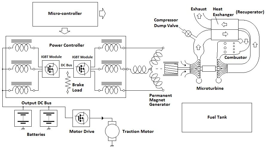
The above diagram illustrates a typical microturbine gas turbine installation. Size and weight may not be the primary design criteria but if intended for automotive use then weight and compactness are important.
Component parts in detail.-
Compressor. Unlike larger aero or industrial engines, microturbines exclusively adopt the use of the centrifugal type compressor wheel and surrounding diffuser. One microturbine aspiring manufacturer Bladon Jets infer in some of their publicity material and illustrations that a miniature axial type compressor has been produced and it surpasses or supersedes other designs. No significant evidence has ever been seen by the author to substantiate the claims that such a working unit actually exists. A photogenic and aesthetic design has certainly been publicized and used in the promotion of the concept hybrid electric super-car the Jaguar XC-75 but this was some five years ago (2010) and in that time no genuine media or footage of its operation has been seen??
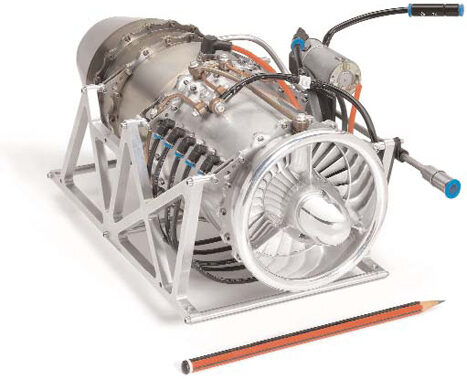
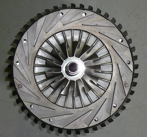
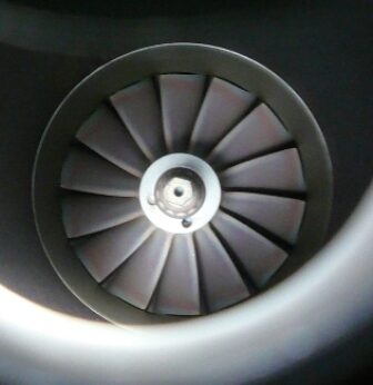
A centrifugal compressor consists of two major components the impeller wheel and diffuser. The impeller wheel consists of a flat cone or disc shape wheel with a number of radially disposed vanes mounted on it. Between the vanes channels are formed that carry air outwards to the edge of the wheel. The vanes may be split in to long and short types, the longer of the two emanating from close to the wheels cent re. Depending on the design of the wheel the vanes may be curved in the direction of rotation in order to alter the aerodynamic characteristics of the wheel. An additional component is added to the wheel in the form of a ring of fan like blades known as rotating inlet guide vanes. These additional vanes line up with the radial vanes and guide the air flow in to the wheel. Air is drawn in by the guide vanes towards the centre of the wheel and under the action of centrifugal force flows out to the edge of the wheel at high speed. The effect of this is to raise the static pressure and velocity of the air flow.
Around the circumference of the compressor wheel is mounted a ring of fixed radial passages formed between either curved vanes or wedge shaped blocks. These radial passages form diverging nozzles or simple venturi that slow down the fast moving air that is thrown out of the periphery of the compressor wheel. The combined action of the compressor wheel and diffuser raises the static pressure of the air by up to a ratio of 4 to 1. The air having been compressed as become heated to up to a temperature of 180 degrees C.
Compressor wheels are usually constructed from alloys of aluminium and may be CNC machined from solid or cast. Various corrosion resistant or finishing treatments may also be required.
Sometimes a space is built around the diffuser to collect the air and pass it to the next stage of the microturbine usually the recuperator, this is known as a volute. The volute is snail shell in appearance and is a common part found in many turbo-chargers. The microturbine may be build of discrete assemblies such as turbo-machinery with gases ducted to and from a separate recuperator and combustor assemblies.
Combustor. The combustor or combustion chamber is the region in which heat is added to the working cycle of the gas turbine. Heat like in any other engine is the source of energy that is ultimately converted to mechanical work. Fuel is burnt either in gaseous form or a form originating from a liquid state i.e. as a vaporized gas and atomised mist.
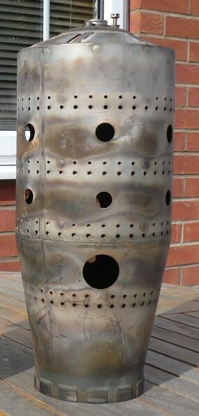
In microturbines combustion chambers take the form of either a annular region wrapped around the hot end of the engine or a single can type vessel mounted two one side of the engine rotating axis. One or more injectors or nozzles are used to admit fuel in to a zone within the combustion chamber with which a portion of the air incoming from the compressor is mixed. The combustion chamber is lined with a perforated cylinder that admits the air in to differing zones. Generally there is a zone close to the injector (s) where the primary combustion takes place. Here a steady flame is held in suspension by the action of re-circulating air currents often arranged to form a vortex or swirl. Downstream of the primary zone a secondary zone mixes additional air to cool the heated gases emerging from the flame. The orientation and sizes of the holes and perforations in the combustor liner depict the flow or gas currents within it. These currents and help stabilize the flame and prevent extinction during transients. Only a portion of air passing through the engine is used to support the combustion process in a microturbine, the remaining air (around two thirds) is mixed with the combustion exhaust to lower its temperate to that suitable to feed the turbine.
Fuel is injected in to the combustion zone by means of a nozzle or burner assembly. Fuel may be gas or a liquid. In gaseous systems the gas may be pre-mixed with a portion of incoming air or allowed to merge with it at the point of injection. Liquid fuel is either injected through a small nozzle to create a fine atomised spray like that from an aerosol nozzle or it passes though a small chamber where it is vaporized by the heat from the surrounding combustion. In the case of atomising burners a small additional atomising burner is used to create an initial flame to start the vaporizing process. Certain designs of atomising burner may also feature the addition of an external source of moderate pressure air to assist in atomisation particularly at low fuel flows.
The popular Capstone C30 microturbine employs a wrapped-around annular type combustor fitted with three burners. At low loads below 6Kw only one burner is operating and the remaining pair are brought in to operation above 6Kw as increased power required.
Other microturbines employing a single can combustor are fitted with a single burner. The advantage of a single burner is it may be removed and services as one complete unit with minimum disturbance of the rest of the microturbine engine assembly.
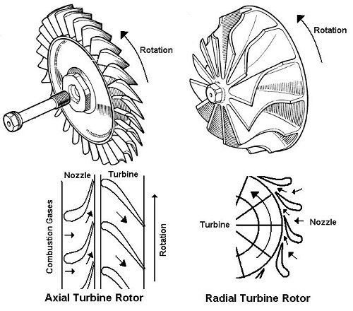
The turbine wheel in its basic form is similar to the compressor wheel and operates in reverse. In the compressor mechanical work (supplied from the turbine) is carried out to raise the pressure of the incoming air and subsequently it is also heated. Gases passing through the turbine assembly lose pressure and also temperature as work is extracted from the stream and transmitted via the shaft to the compressor and an external load.
The turbine wheel is known as a radial inflow device and takes the basic form of an impellor shape and is similar those that are found in automotive turbochargers. There are in fact two types of turbine wheel found is gas turbine engines. A second type of wheel is known as the axial flow turbine and consists of a hub surrounded by small individual blades. This type of turbine is common in larger commercial gas turbines either for aircraft power-plants, aero-derivative units or large industrial units. In the smaller microturbine format the radial inflow wheels are more common due to an improved tolerance of running clearances and suffer less of a performance deficit when compared to the use of axial units. Also in small gas turbines it is common two use two stages of axial flow wheel that is of course more complex to accommodate. In a small engine a single radial wheel may do the work of two axial stages.
The radial turbine wheel is surrounded by a component known as a nozzle. A ring of individual converging orifices form nozzles surrounding the turbine wheel that direct the hot combustion gases in to it in the direction of rotation. The turbine and the nozzle must be made of a high temperature corrosion resistant steel alloy such as Nimonic. These metals are very tough and are required to withstand the high turbine inlet temperatures at high power outputs with long life. The hot combustion gases impinge on the turbine blades and pass between them toward the centre and are guided along the shaft axis by curved portions of the blade. The exhaust exits the turbine along the shaft axis.
The compressor turbine rotor group is supported by special high speed bearings. In conventional small gas turbines ball race bearings are common place that are lubricated by oil jets from a re-circulating oil system. Synthetic turbine oil is stored in a reservoir and that may also form a sump beneath the bearing assembly. An electric motor driven pump pressurizes the oil flow that is fed to one or more of the jets. A oil cooler may also be used to remove heat picked up by the oil as it passes though the bearings. Bearings may consist of angular contact races biased with a spring (to dampen rotor dynamics and resonances) or by a single ball race to locate the shaft axially and a second roller race locate the opposite end racially. These two differing arrangements allow for thermal expansion of the shaft and bearing carriers. Certain bearing arrangements may also make use of an oil film surrounding the bearing race to act as a dampening medium. High speed turbo machinery are prone to resonance and vibration effects as there is interaction of the turbine wheel mass, compressor wheel mass and the flexibility of the shaft and mountings. The speeds at which these effects occur are known as critical speeds. As a small gas turbine engine is started and accelerated the rotor may pass though oscillating and whirling modes, the engine must not be run continuously at these critical speeds ranges. It has to be remembered also in many microturbine applications the electrical generator also forms a high speed machine with it’s own rotor dynamics.
In engines adopting oil lubrication, seals are required to prevent loss of oil in to the gas flows and exhaust. Common seals in small engines may be labyrinth types often requiring some sort of partial pressurization and spring loaded carbon face seals.
An unusual design is built by the Capstone Turbine company. Capstone adopt air bearings to support the gas turbine rotor shaft and the generator rotor. The Capstone is an ingenious design, no oil system is required reducing maintenance costs and complexity. There is also no seal components normally required to prevent oil contamination of the exhaust gases.
Air bearings operate by trapping air between the high speed shaft and a surrounding foil medium. A boundary layer effect holds the shaft in place, this only occurs at high speed so the shaft must be spun up quickly to “lift off” and also “grabbed” and halted quickly during shut down. Air bearings are sensitive to shock and so the engine assembly must be resiliently mounted to prevent penetration of external low frequency vibration.
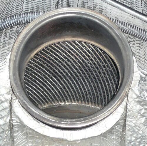
Recuperator. The recuperator is an essential part of a microturbine generator, without it the efficiency of the unit is simply to poor and not able to justify the manufacturing, installation and running costs compared to a piston engine alternative. The recuperator is also a tricky component to produce and operate.
In the 1960s a special type of recuperator was built for automotive gas turbines that consisted of one or two rotating glass/ceramic disc matrixes through which the hot and cold gases were alternately passed. The gas sealing and durability of this component proved very difficult to achieve economically and partly contributed to the downfall of the automotive gas turbine during that era.
A static recuperator consists of a heat exchanger matrix not dissimilar to a automotive inter-cooler radiator. There are two separate gas flows through the unit, one fed from the compressor outlet and the other fed from the turbine outlet. The matrix is constructed from heat resistant steel and may form a separate individual component mounted next to the engine or may be integrated with it. The metallic heat exchanger has a given thermal heat capacity that results in thermal inertia when transients are experienced thus slowing the overall response time (Acceleration and deceleration) of the turbine unit.
Heat recuperator exchangers in small gas turbine systems pose a number of problems particularly in terms of response times when changes in electrical load are experienced. It is the function of the engine control system to ensure that a stable output power supply is maintained and that the gas turbine and recuperator assembly are not subject to unnecessary thermal transients. To deal with this problem there are a number of potential solutions-.
1. A storage battery system may be used to “buffer” the flow of energy to and from the gas turbine. The heat exchanger may have a large thermal inertia and so the engine will be slow to accelerate and decelerate as load demand changes (As it absorbs and releases heat). The battery via an inverter may be used to temporarily take up the electrical load and the engine speed and load “ramped” up and down to “catch up” with the demand and stabilize with it.
The storage battery system takes a form similar to that of an uninterruptible power supply unit (UPS). When the turbine output cannot meet the power demand then the battery bank takes up the task maintaining continuity of supply like a UPS. The battery is also used for starting and cool-down cycles.
At shut-down a Capstone micro turbine engine actually runs on the stored energy contained in the thermal capacity of the recuperator thermal mass! An electronic software control system manages the flow of energy from the generator, as the recuperator cools the generator becomes a motor and maintains a constant turbine speed (and hence cooling air flow) until the turbine outlet temperature of the unit has reached an acceptable figure for shut down. Careful thermal management of the recuperator is essential to maintain a long service life and reduce thermal shocks to a minimum. This process takes some 10 minutes!
2. A breaking resistance inside the power controller system may be used to dissipate excessive electrical energy if the applied load is rapidly reduced. The control system will throttle back the turbine fuel supply (And hence the heat input to the working cycle) and it will decelerate reducing output as the heat in the recuperator is expelled and the system stabilizes at a lower power condition. Unlike a simple cycle gas turbine without a heat exchanger, this type of system cannot instantaneously respond to load changes and so a management system must be used.
3. The generator output may be fed into the electrical grid system that acts as a load placed upon the turbine. The grid system may be considered an “infinite bus-bar” system i.e. it has a low impedance and the excess generated power is allowed to flow into the grid for use elsewhere. During start-up and cool-down the grid system supplies energy to the turbine. This energy flow process requires precise control by the micro-controller based system.
4. An additional way to rapidly dissipate unwanted energy in a micro-gas turbine is to bleed air from the compressor of the micro-turbine. If the engine is supplying high load and running at maximum rpm and then experiences a large load reduction an air bleed may be employed to divert air and hence gas away from the turbine reducing the spinning force and thus reducing rpm. A dump valve may be fitted to a ducting system that collects air from the compressor diffuser and exhausts it to atmosphere to temporarily stabilize engine rpm.
5. In order to operate under light load a micro-turbine may employ a burner switching system that operates the combustion system on a reduced number of burners during low load periods. This will promote stable burning and reduce the risk of flameout when compared to operating multiple burners close to their lower limit of stable operation. This will also improve the likely exhaust emissions as a more precise burn occurs.
The modern microturbine engine is made possible by the addition of an sophisticated electronics. The electronics performs two significant tasks firstly to control the functioning of the gas turbine and secondly to convert the electrical power generated in to a useful format. A third task is to process the electrical power in reverse from an external source to start the engine.
A microprocessor is used to monitor and control the gas turbine engine. A number of sensors are fitted to the engine such as compressor inlet temperature, turbine outlet temperature, compressor speed, generator output and so on. Values from these sensors feed in to a software program that runs the engine within prescribed limits and ensures it is not overloaded. An operator control panel will also fed commands to the microprocessor and this may be achieved locally at the engine enclosure or remotely from a control centre far away.
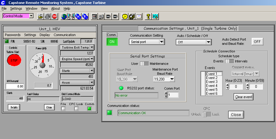
Control and instrumentation of many stationary micro-turbine engines lends itself to automated and computerized control. Also remote control of multiple units is possible over data links such as modem networks, IP networks and the Internet. A Windoze graphical user interface (GUI) is used to access all engine controls and parameters. A computer communicates with a local engine mounted micro-controller responsible for interfacing commands and providing indications from the turbine. A manufacturer’s proprietary protocol is used to pass data to and from the micro-turbine installation over the data link. A single computer remote from the installation may be in charge of hundreds of micro-turbine installations. An installation may also have an operator control panel for “Local” control and diagnostics.
Capstone micro-turbines incorporate a sophisticated GUI. Simultaneous windows display basic engine parameters, communication protocol and advanced engine and generator statistics. Devices that form the engine installation are identified with “personality” modules so that the remote system may interrogate the hardware installation and display the modules in use. Differing builds and installations will vary in terms of hardware modules and so the micro-controller and software control adapts to the specific configuration for the application e.g. HEV (Hybrid electric vehicle), grid connect, stand alone etc. Engine and power system health is continuously monitored, in the event of a fault the system will alarm and if necessary shut down the engine. A fault and event history log is kept on file for later analysis. The engine running hours and starts are also recorded so a complete lifetime record is kept of the engine’s use.
As well as standby power and grid connect applications micro-turbines are able to be employed in vehicles. Electric vehicles may be fitted with a micro-turbine in order to provide a means of extending the useful range of the vehicle. The micro-turbine is used to provide power to maintain the charge of batteries on-board the vehicle and also augment greater power when cruising at high speed. The micro-turbine may be operated on a range of liquid fuels including diesel. In the case of diesel the vehicle may emit lower emissions due to the cleaner burning of the gas turbine compared to a diesel engine. Vehicles fitted with micro-turbines may be referred to as “Hybrid” vehicles, however a “Hybrid” vehicle generally uses electric motors and a piston engine to both drive the wheels. A vehicle fitted with a micro-turbine power-plant may be considered to have electric only propulsion as it is only electric motors that are physically connected to the wheels. Micro-turbines are unsuitable for use with mechanical couplings to anything other than high speed alternators. An electrically propelled vehicle fitted with batteries and a micro-turbine may be considered to be an electric vehicle with a “Range Extender” fitted.
The current generation of micro-turbine generators are suited to commercial vehicles and buses due to significant weight and bulk (Mainly due to the batteries and recuperator). Vehicles used for public transport and deliveries particularly in big cities where the authorities may impose exhaust emission regulations are able to exploit the advantages of micro-turbine engines namely better exhaust emissions and lower noise pollution when compared to diesel engines.
Faced with the prospect of fitting a micro gas turbine and associated hardware car size represent more of a installation challenge. A complete system is more bulky than the original piston engine set up. The batteries even if used for “peak” power (e.g. acceleration) represent much weight and current micro-turbine designs are also heavy and the vehicle still needs to carry liquid fuel in significant quantities.
Engine accessories.
Microturbines generally do not employ any kind of accessory gearbox unlike an aero-derivative engine or APU. Accessory gearboxes may be used to drive the gas turbine accessories such as oil pumps (if oil lubricated), fuel pumps and cooling fans, however they are complex and expensive, an alternative is to use individual electric motors. Electric motors may be used to drive all accessories including air compressors for atomisation and gas compressors in the case of natural gas fired systems. The use of industrial grade standard types of motor helps reduce costs and ease maintenance. An additional advantage is electric motors may be easily controlled and in the case of a liquid fuel pump the motor speed itself may be used to meter the fuel flow to the engine, negating the need for a special proportional spill valve. This may be achieved by varying the power supply to the motor under the control of a microprocessor control system. The liquid fired Capstone unit works in this way.
Ignition system.
An important part of any gas turbine engine is the ignition system. A high energy discharge system is common with many microturbine designs. Similar to aviation types a special capacitor discharge exciter is used to send a high energy pulse to a special surface discharge igniter plug. The exciter consists of a capacitor and inverter charging system that charges up to approximately 2000V. The action of a electronic circuit or sealed discharge gap fires when the capacitor is charged up and a fierce spark is created over the surface of the plug.
An alternative to the high energy discharge system is to use a glow plug system. The innovative IHI (Ishikawajima-Harima Heavy Industries) Dynajet 2.6 model uses a conventional diesel type glow plug to ignite the liquid fuel spray inside the combustor.
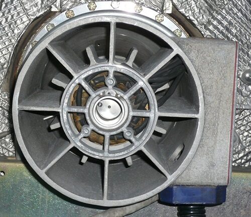
Generator.
There are two basic types of generator that may be found fitted to microturbines, the high-speed directly driven generator or a conventional low speed alternator driven via a gearbox.
Microturbines employing a free turbine two shaft layout may use a reduction gearbox to drive a normal two or four pole synchronous machine. The advantage of this is a near conventional off the shelf alternator may be used but it will require a reduction gearbox that is specially built to handle the high input speed from a turbine unit typically 50,000 rpm. The gearbox will also require a re-circulating oil system that will add complexity to the engine.
Microturbine engines may drive a generator directly at the running speed that may be up to 100,000 rpm. The advantage of this arrangement is the alternator is much smaller in size due to the much higher operating frequency. In any electrical generator, the electromotive force (EMF) or output voltage produced is proportional to the rate of change of the magnetic field inside the generator. If the alternator turns faster the rate of change increases, as the speed doubles (ignoring losses) the output voltage doubles also. For very high speed machines the size is greatly reduced. A generator fitted to a Capstone C30 30Kw unit is barely larger than a tea mug, weighs around 2 kg and is built in to the air intake. A conventional 50Hz two/four pole brushless alternator turning at 3000/1500 rpm may measure some 500mm x 400 mm and weigh 90kg!
The catch with high speed generators is they must be precisely manufactured and they require external electronics to process the electrical output in to a useful format. Very large forces may exist in high speed machinery, the rotors must be specially designed and very well balanced.
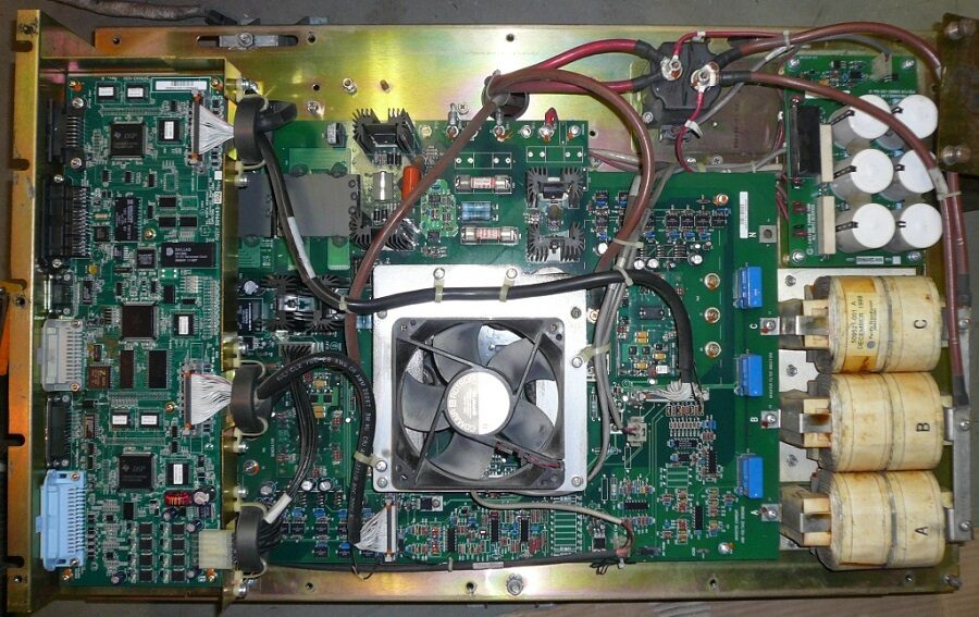
Microturbines employ inverters to process the generator output current to suit the required application. The Capstone features a permanent magnet generator (PMG) that is connected to a special unit known as the Digital Power Controller (DPC). The PMG supplies a three phase high frequency current of up to 750V to the DPC where it is converted to a DC bus. It is then depending on the application back to a low frequency AC feed for connection to a load or the power grid. A special HEV version of the DPC is able to feed a DC current for the charging of vehicle traction batteries.
Starting of the Capstone micro-turbine units is achieved by driving the PMG unit as a synchronous motor. The electronics used to convert the output current of the PMG are also used to drive the alternator in a sequence necessary for it to rotate the micro-turbine at relatively high speed. For start up, the rotor may first need to be “lifted off the bearing” in air bearing systems typically at 25,000 rpm, the engine is then rotated at light up speed of 35,000 rpm and once lit, accelerated to idle of some 50,000 rpm. A maximum operating speed may be in the order of 96,000 rpm. Once at idle the heat exchanger is allowed to absorb the exhaust heat. During shut down, the engine may also be rotated by the generator for a period necessary to bring down the heat exchanger temperature to an acceptable minimum before a complete shut-down, this will ensure long life of these components. This process may take up to 10 minutes depending on ambient conditions. Stopping the engine with a hot heat exchanger is likely to reduce the life of this complex component due to thermal shock and expansion/contraction fatigue.
The fall and rise (and fall again?) of Microturbines
There is a possibility that microturbines may become common place as range extenders in electric vehicles (EVs) installed in a Turbine Recharged Electric Vehicle (TREV). But how likely is this? A small rugged, economic, efficient power plant, also producing low emissions is a fantastically difficult thing to achieve! No company anywhere in the world has so far produced anything suitable for the adoption as a range extender in any type of vehicle. Several companies have built prototype vehicles using the Capstone microturbine but the C30 unit is bulky, heavy and relatively fragile. It also required compressed air as an externally supplied service and takes 10 minutes to shut down! Over the past decade trials have taken place with range extended super cars, SUV type vehicles and buses but have they caught on? No!
The mix of skills, experience and expertise needed to develop and manufacture a microturbine is a wide ranging one.
Turbo-machinery; High performance durable and long life turbo-machinery is required probably best produced by a turbo-charger manufacture with an understanding of high speed shaft dynamics such as Garrett, Holset, IHI or Switzer.
Low-emission Combustor; A difficult challenge and from what industry could such a device be derived baring in mind the small scale of such a unit?
Recuperator; A robust long-life component possibly built from expensive materials with potential issues in manufacture.
High Speed Alternator; A bespoke precision device is needed drawing on the experience of high speed drives.
Power Electronics; A manufacturer of AC drives, inverters or high speed motors to take up the challenge? All of this brought together under one roof with the common goal of a mass produced and integrated microturbine system.
A number of companies are making claims regarding microturbine products and publishing impressive CAD drawings and artistic illustrations but where is the substance? Where in 50 years of small gas turbine development by many experienced and “tooled up” companies are the products? Most of them have failed to become cheap enough, durable enough or cost effective?
Automotive and aerospace manufacturers have been producing small gas turbines for many years since the 1960s and very few survive today, in short it’s all be tried before. In static power generation, distributed generation and CHP manufactures have come and gone. What is different today is the potential appetite for a range extender type power plant now exists and the complimentary batteries and electronics continue to improve. Any company that truly develops such a device will make World automotive history. It will be an event more significant than the gas turbine Rover BRM completing Le Mans, the demonstration of the prototype Rover P6 and the Chrysler Turbine Cars, history in the making!
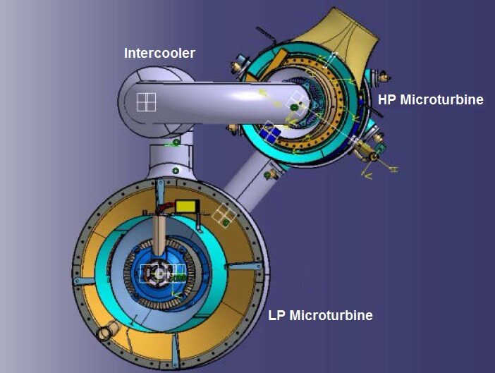
Capstone Turbine the World’s market leader are arguably best placed to bring the next generation of microturbine design in to being. Funded partly buy the US government Capstone have designed a twin spool microturbine concept consisting of two machines a high pressure unit and a low pressure unit connected together. Both machines are fitted with permanent magnet generators (PMGs) and an additional inter-cooler unit feeds air from the LP unit to the HP unit. Twin-spool gas turbines and even triple-spool gas turbines are not uncommon in large scale power generation and aircraft engines but the technique although not new has yet to be demonstrated in a production micro gas turbine engine.
An ingenious concept the C370, the LP microturbine is a development of the large C200 machine, the HP microturbine is a development of the C65 microturbine. The increased pressure through the HP unit means the volume is less and hence a smaller machine can be used. There are challenges though, for best efficiency the HP turbine inlet temperature is higher than in a single shaft unit. Capstone propose a dual metal (bi-metal) radial inflow turbine wheel featuring bonded on blade tips of a superior metal that can withstand the high temperatures at this point. As with all microturbines, service life and durability are key attributes for a successful product. The engine also features a water-cooled inter-cooler to cool the air charge received by the HP compressor, this is necessary to improve efficiency and also enable the air-cooled PMG to operate in the air intake.
Other areas of development of a twin spool machine are the electronics requiring two sets of digital power management and a complex software and hardware control system to keep the engine running at optimum speeds at part load. The engine spools will have to be run at near constant turbine inlet temperatures regardless of load (to protect the recuperator units) and the spool speeds varied as in the case of the single shaft units.