Some Odd British Gas Turbine Units
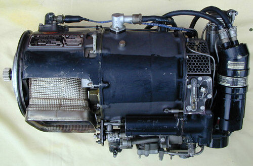
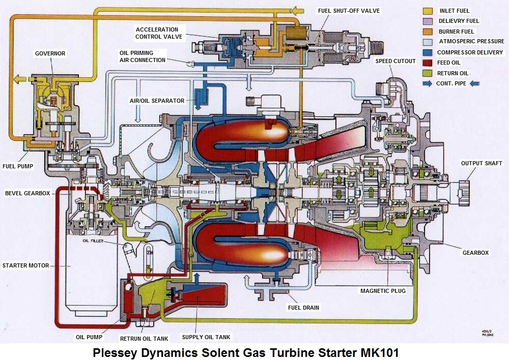
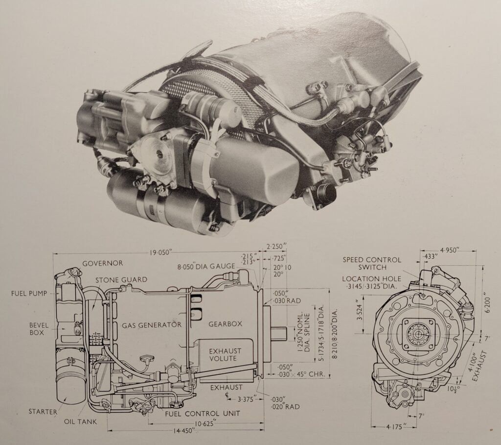
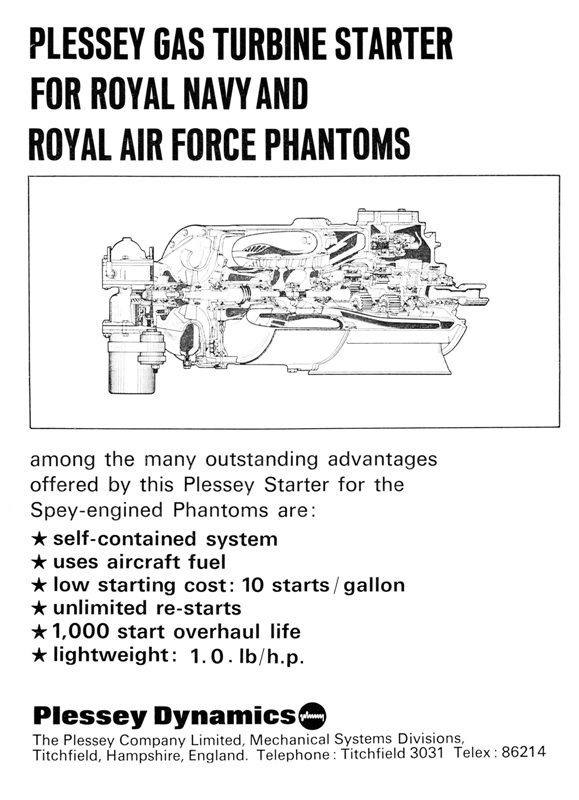
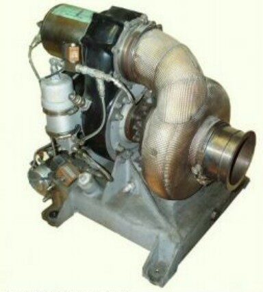
The Plessey Dynamics Solent Mk101 gas turbine starter(GTS). A small turbo-
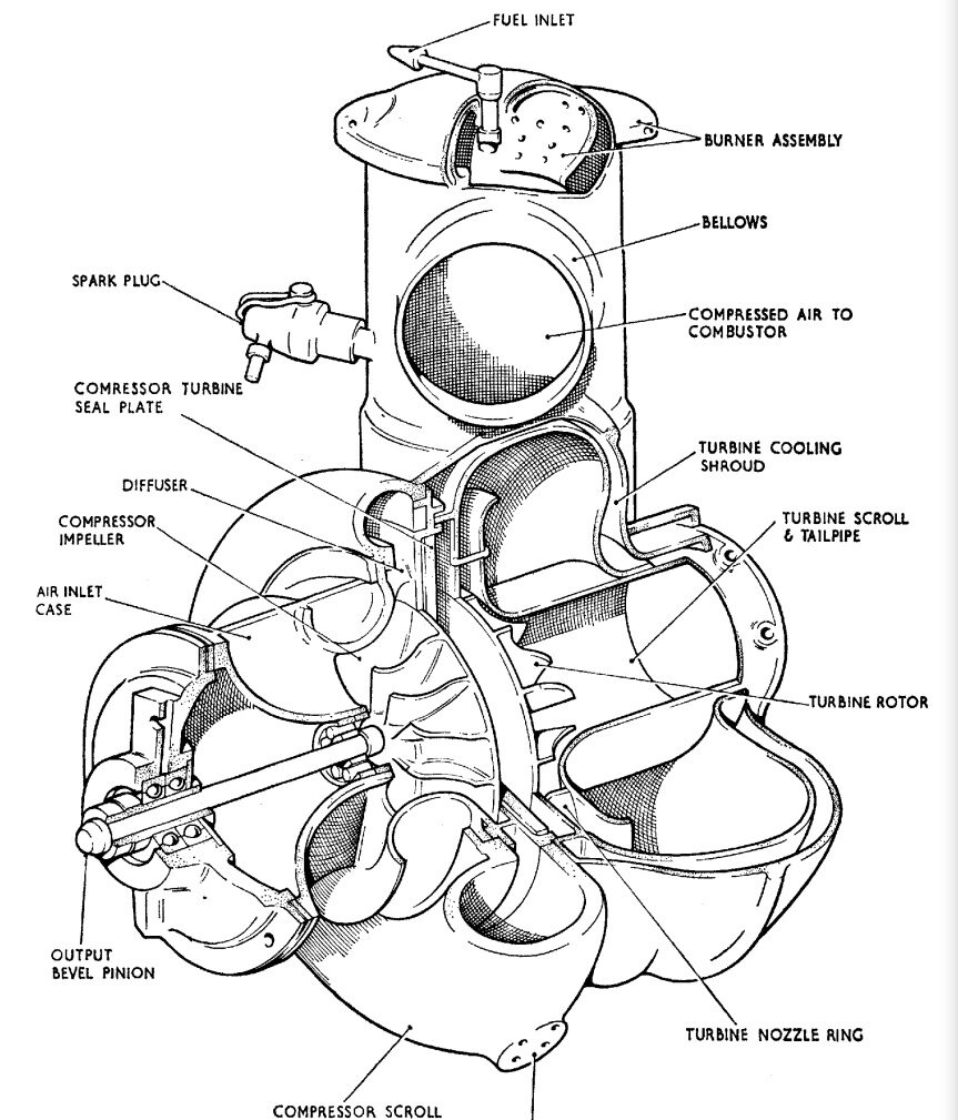
The Solent engine comprises of a centrifugal compressor feeding a classic wrap around reverse-
The Solent features spill type simplex atomising burners that are fed from a gear type fuel pump. The pump delivers a fuel flow in excess of the engine requirements and control of fuel metering is effected by an acceleration control valve. The acceleration control valve is activated by compressor delivery pressure, as the Solent is started, lights and accelerates, building air pressure opens the valve and greater fuel flow results. The Solent is governed by a simple fly-
The Solent accessories consist of the simple gear fuel pump and a starter motor driven from the compressor shaft. The starter motor and fuel pump are mounted at the front of the engine (Compressor air-
A clever feature of the Solent gas turbine is the oil system. The engine uses a simple one-
The engine is fitted with two high-
The output reduction gearbox is fitted with a special cutout mechanism. A second flyweight governor opens a set of electrical contacts to signal to the aircraft starting system that the Spey engine has successfully started reached self sustaining speed and so the starter may be shut down. If the Spey engine fails to start, it will not reach self-
The Phantom aircraft are retired now, it must have been quite a spectacle to watch and hear a Solent in action! This small engine will spin up very quickly and howl away as the big Spey engine catches up. I understand the Solents were prone to various failures, malfunction of the electrical control circuits or the cut out switch could result in the power turbine over-
For hobby and experimental use the Solent can be fun but a challenge to accomplish useful tasks. They have been fitted to go-
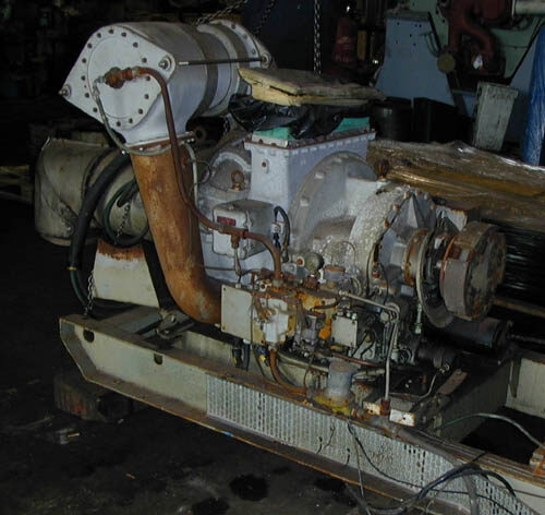
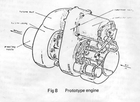
Having built the intermittently rated Solent, Plessey did investigate modifying it (with the addition of various oil pumps) for use as an APU generator. A white paper was written that describes how it was done. I understand only one prototype (pictured above) was ever built.
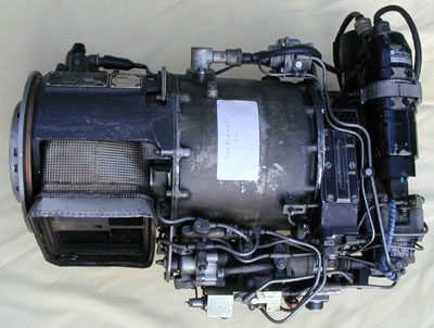
Plessey Solent Solent Specification
Power Output...............................................….…………..........70 Bhp (1 minute duration)
Rpm................................….……...........…..................…..…….................Centrifugal Impeller
Combustion Chamber..........….……......Reverse flow Annular with 8 Simplex Burners
Gas Generator Turbine.................….….....….……………………..………….................Axial Flow
Power Output Turbine..................Axial Flow with 11:1 epicyclic reduction gearbox
Layout..................................Twin shaft, spring-loaded angular contact main bearings
Starting..........................................................................….…………............DC Starter Motor
Ignition..............................................................................................Two HT Igniter Plugs
Fuel System................Gear Pump with Centrifugal Governor, Acceleration Control
Lubrication.....................................One-Shot pump powered by compressor bleed air
Application..........................MD Phantom F4 GTS, Experimental Ground Power unit
Austin 250 gas turbine engine
Around 1950 the Austin car company experimented with gas turbines and initially developed a unit for fitment to a car. This wasn’t really successful so they turned to the development of a stationary engine and the “Austin 250” model was produced. The simple engine consisted of a single stage centrifugal compressor driven by a two-stage turbine. The layout and components seem to resemble some industrial turbo-charger components. An external single can combustor was fired with either liquid fuel or natural gas. An unusual feature of the burner system was the igniter plug was built in to the burner head. The engine featured a heavy duty helical cut gearbox with accessories mounted on it. The engine used a large diesel type starter motor and the whole engine assembly sat on a large flat oil-tank. Kerosene burning engines were fitted with a simple gear pump and governor arrangement, gas burning engines would have a governor valve and an external gas compressor.
Engines were mostly used for power generation and were fitted to a 200KVa alternator, a few were also tried as fire-fighting pumps.
A gas fired unit was found a few years ago that had been decommissioned from a power station. No liquid fired unit in working order has been seen to date.
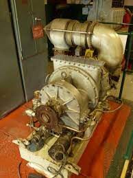
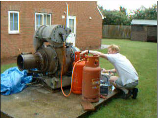
Austin 250 Gas Turbine Specification
Power output..................................................….………………………………….....250 Bhp
RPM........................................................….……………………………………............29,200
Compressor...............................................….……………….........Centrifugal Impeller
Combustion Chamber...............................….…………….......Side Entry, Single Can
Turbine..........................................................….………………………….......2 Stage Axial
Layout....................Single Spool with reduction gearbox, non axi-symmetrical
Starting........................................................….……………….......Lucas Starter Motor
Ignition..........................................................….……………........High Energy Igniter
Fuel System......Gear Pump with Centrifugal Governor or Natural Gas System
Lubrication................................................….………..........Dry Sump with oil cooler
Applications..................…….........Stationary Engine, Water Pump or Generator
R H Philips Turbine Technology TTL gas turbine compressor
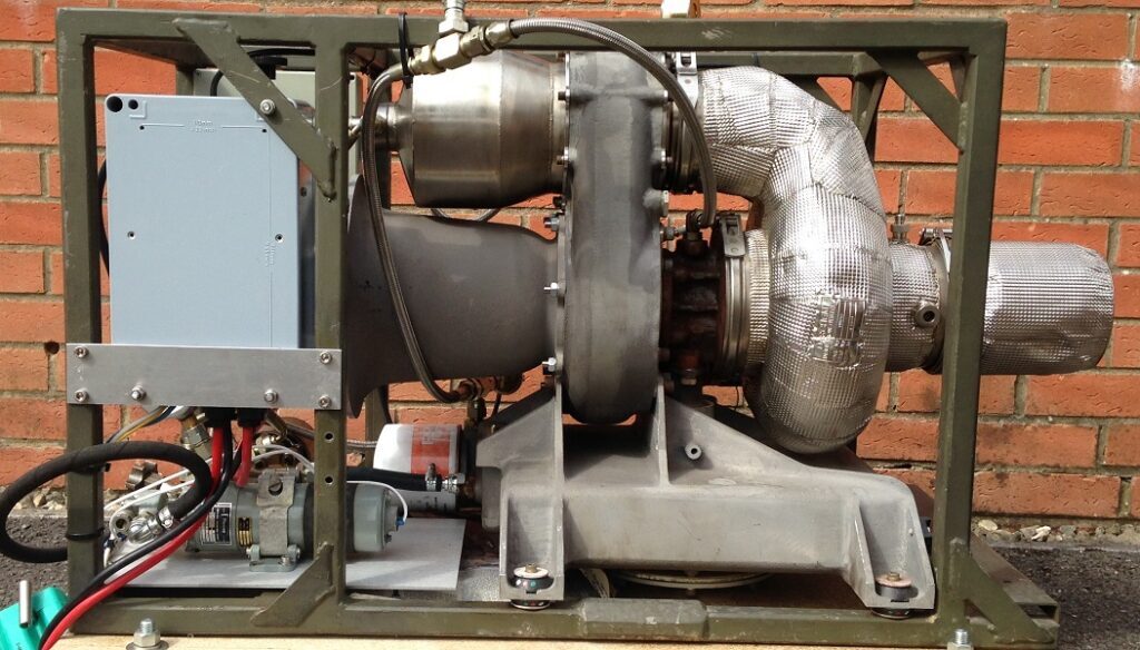
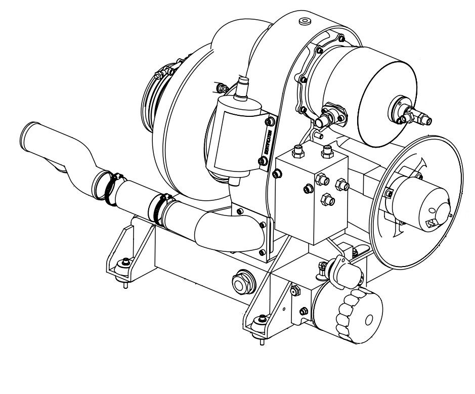
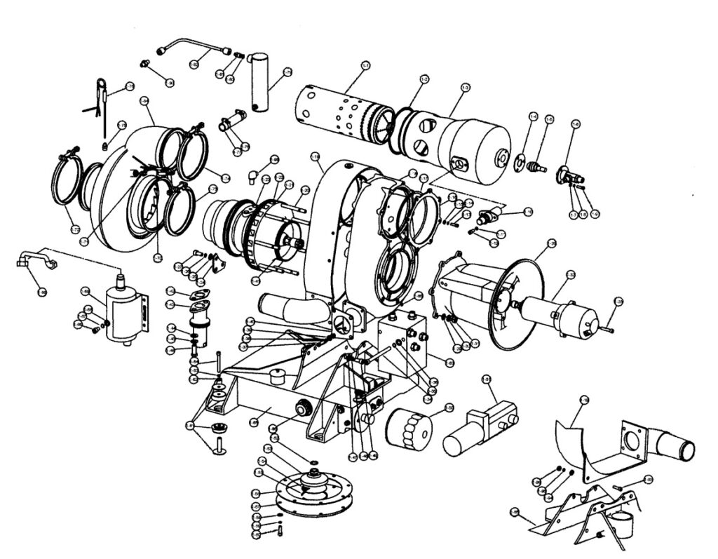
In the 1980s Belfast Queens University embarked on a research project to develop a low cost disposable turbo-jet engine in partnership with Normalair Garrett, although Holset may also have made a contribution. A simple unit derived from a turbo-charger rotating core with re-worked vanned diffuser and a vanned turbine nozzle. A pioneering idea at the time as it was unlikely much work like this had been done before. Now helped by the Internet enthusiasts all around the World have built many demonstration engines and have even powered go-kart like vehicles to amazingly high speeds with turbochargers.
The engine has been developed in to a stationary unit for use as a smoke generator and air compressor. The use of a turbo-charger core keeps costs down and ensures a tough and robust unit for military use.
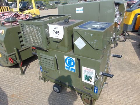
Engine sets were built up in enclosures by R H Philips and son of Sussex.
These units have been adapted as air producers for "jump starting" the Merlin helicopter in case it's won internal APU is unserviceable which would render the helicopter itself grounded.
RH Philips/TTL Gas Turbine Specification
Power output.................................................................................estimated 75 air hp
RPM..............................................................…....………..……….………………............85,000
Compressor.....................................................….……………….........centrifugal impeller
Combustion Chamber...............................….…………....…..........side entry, single can
Turbine...............................................................….………………………….......1 Stage radial
Layout...........................single spool automotive turbocharger with plane bearing
Starting.............................................………………....electric starter motor with bendix
Ignition...................................................................….……………........high energy igniter
Fuel System......................................................electric pump with electronic control
Lubrication....................................................................wet sump with electric pump
Applications....................……..................................air producer, smoke/fog producer
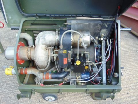
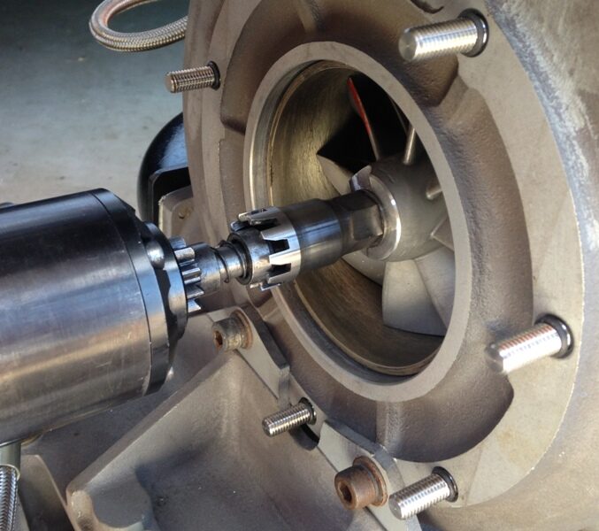
Perkins Mars gas turbine (Solar T41)
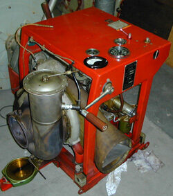
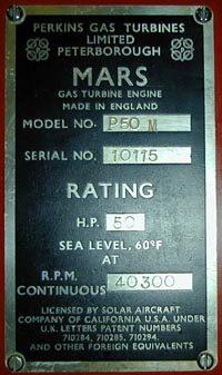
The Perkins Mars gas turbine is a British licence built version of the American Solar T41. A very simple stationary unit featuring a centrifugal compressor, radial inflow turbine and can type combustor. A rival to the Rover 1S60 producing 50HP. These engine could be found in use driving water pumps, electrical generators and also as instructional sets for colleges and universities. This type of engine was built long before the smaller rc-model type turbojets that may be adapted for laboratory use today.
A hand crank unit requiring some considerable effort to achieve self-sustaining speed. A simple magneto created sparks to light the engine as the crank handle was turned.

T41/Mars Specification
Power Output....................….……………….…….………………………..........50 hp
Rpm.....................….…………………………......….…...……........................40,000
Compressor..........…..…………….………………................Centrifugal Impeller
Combustion Chamber..….………….……….................Single Can Combustor
Turbine.....................….…………………….....…................Single Radial Inflow
Layout.............................Overhung, Single Spool, non axi-symmetrical
Starting........................….………...........Hand Crank or Starter Generator
Ignition....................................….……………..........High energy or Magneto
Fuel System..............................Gear Pump with Centrifugal Governor
Applications............Water Pump, Ground Power Unit, Airborne APU
instructional engine
Hants and Sussex "Auto diesels" STAD 250 low pressure air start MK12
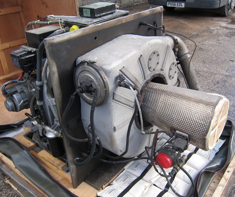
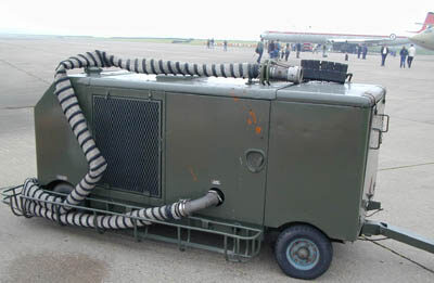
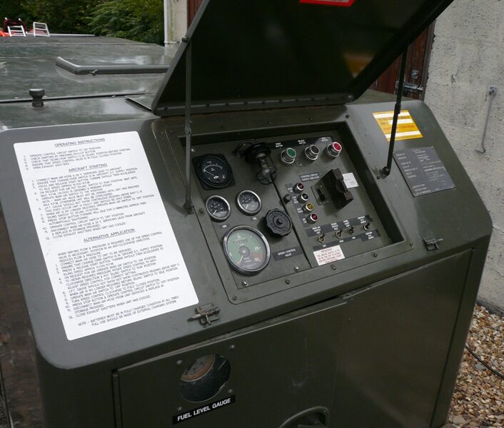
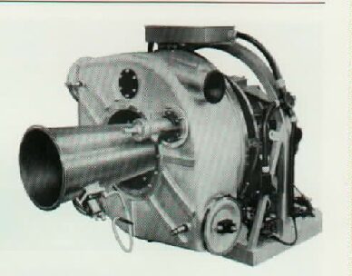
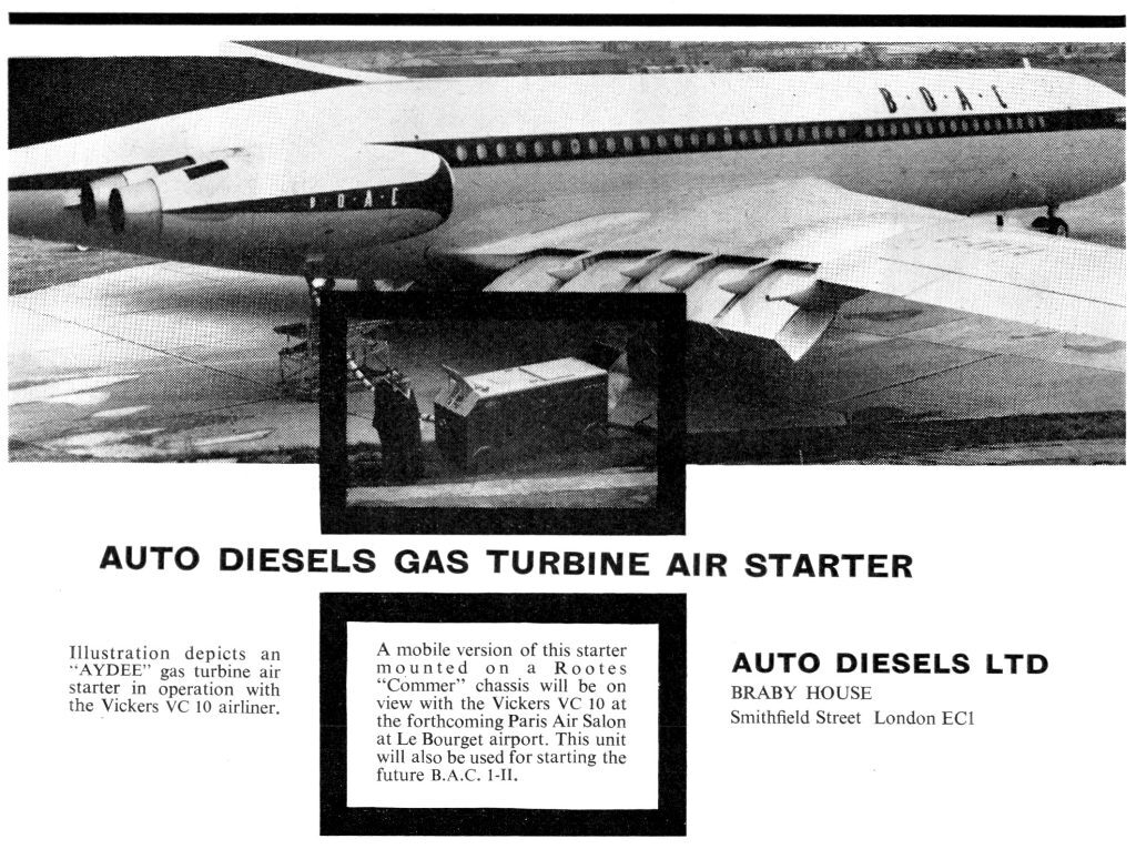
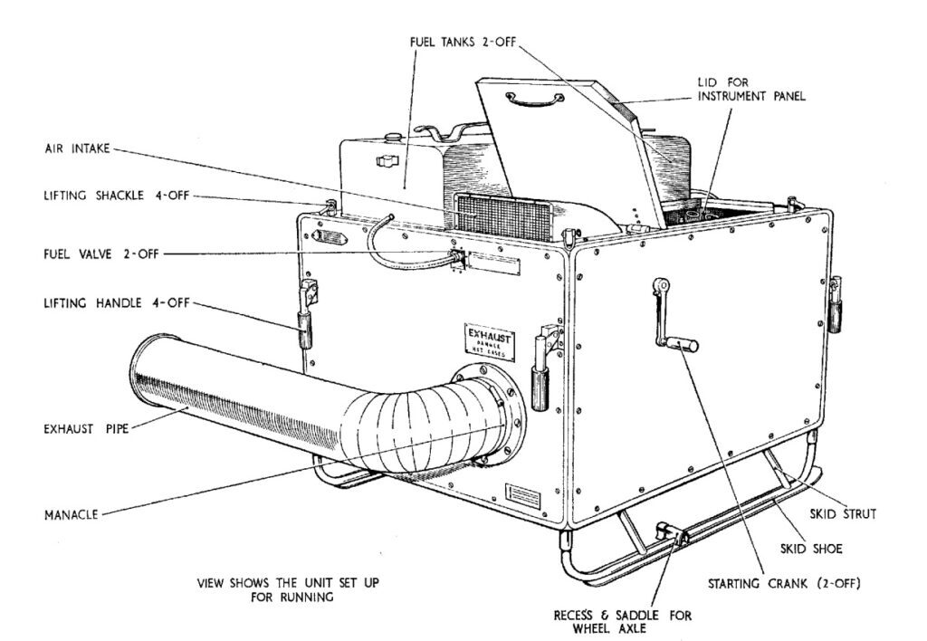
A wonderfully piece of quirky British Air Ministry engineering the Hants and Sussex STAD 250 sold by Auto Diesels Braby known as the LP Starter MK12A and MK12L. A heavy duty stationary gas turbine engine developing the equivalent of 250 air horsepower. The gas turbine was trailer mounted and towed around the airfield to the awaiting aircraft to be started. A large hose conveyed the compressed air to the aircraft at a rate of around 120Lbs per minute at a pressure of some 40 PSI.
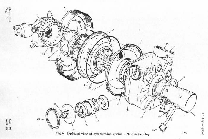
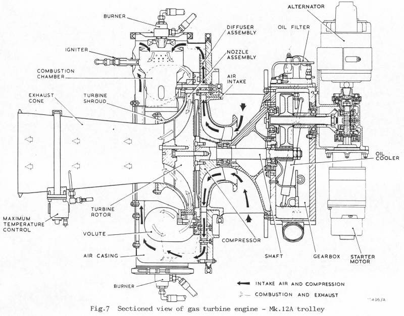
The STAD 250 engine consisted of an oversize centrifugal compressor driven by a large radial inflow turbine. The turbine was fed by two apposing combustor cans through a wrap around volute. A large casing enclosed the burner cans and was fitted with an air bled port and a regulating valve. The single over-size compressor was quite highly loaded in order to provide the required mass flow and pressure. If miss handled the engine could be prone to surging so a regulating valve was fitted to ensure the compressor operating conditions were not exceeded.
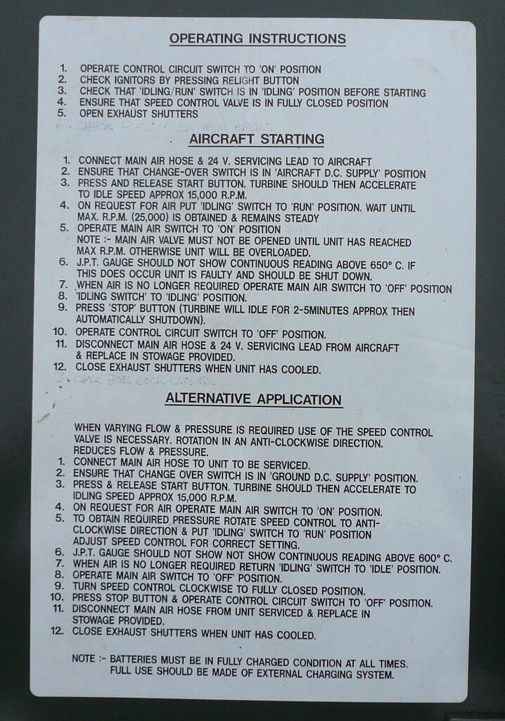
The engine was fitted with two duplex burners and some flow dividing valve work, the engine would initially light off on a moderate fuel flow and then accelerate under greater flow accompanied by a characteristic “howl” from the combustors! The control system on early units was fully hydro-mechanical with a gear type fuel pump and a servo air system to operate various valves and the centrifugal governor. Engines were also fitted with a thermostatically controlled exhaust temperature limiter similar to Garrett engines. Later versions were fitted an electronic governing system and incorporated an electrically operated spill valve.
The engine could be considered a rival to the Palouste air starter and also the American MA1A starting carts that were fitted with the Garrett GTC85.
An apparent weakness with these engines is the starter. A big heavy duty Lucas lorry-type CAV pre-engaged type unit makes hard work of the big high inertia compressor and turbine rotor. Another problem inherent with LP start carts is the environment in which they operate. The units were mostly stored out side that leads to the inevitable corrosion and contamination of the fuel system leading to malfunctions. Also the simple relay controlled electrics could suffer too. The mechanically governed engines were fitted with a number of electrical pressure switches and relays to automatically sequence the start cycle.
The Mk12A unit featured a long trailer assembly with the engine stood in the middle and an exhaust silencer at the back and a fuel tank and control panel at the front. A MK12L unit featured the engine mounted at an angle to reduce space the silencer omitted.
H&S Auto Diesels STAD 250 Specification MK12A
Output....................................250 Air Horsepower (2.2 Lbs/s @ 42 PSI)
RPM(Full).......................................….…………………………….................25,000
RPM (Idle)………....…..…………………………………………………………………..15,000
Compressor..................................................Oversize Centrifugal Impeller
Combustion Chamber.......................................2 Reverse Flow Can Units
Turbine......................................................................Radial Inflow Impeller
Layout.............................................Single Spool with Accessory Gearbox
Starting...................................................….…………………..........Electric Motor
Ignition.......................................................................2 High Energy Igniters
Fuel System.............................Mechanical Pump with Electronic Control
Lubrication.........................................….………………………................Wet Sump
Accessories.........................................….…………………............24V Alternator
Application............................…………….....LP Starting Cart MK12A and L
